Facebook Twitter LinkedIn YouTube Menu Search Arrow Right Arrow Left Arrow Down Arrow Up Home Arrow Next Arrow Previous RSS Icon Calendar Icon Warning Icon

How to schedule

To schedule private education for your group, contact:

Dale Shuter, CMP
Meetings & Expositions Manager

+1 314 993 2220, ext. 3335
dshuter@easa.com

1 hour of training

$300 for EASA Chapters/Regions
$400 for member companies
$800 for non-members

How a webinar works

All EASA private webinars are live events in which the audio and video are streamed to your computer over the Internet. Prior to the program, you will receive a web link to join the meeting. 

The presentation portion of the webinar will last about 45 minutes, followed by about 15 minutes of questions and answers.

Requirements

  • Internet connection
  • Computer with audio input (microphone) and audio output (speakers) appropriate for your size group
  • TV or projector/screen

Zoom logo

The Zoom webinar service EASA uses will ask to install a small plugin. Your computer must be configured to allow this in order to have full functionality. Please check with your IT department or company's security policy prior to scheduling a private webinar.

Private Webinars

EASA's private webinars are an inexpensive way to bring an EASA engineer into your service center, place of business or group meeting without incurring travel expenses or lost production time.

Achieving proper alignment by detecting and correcting soft foot

Achieving proper alignment by detecting and correcting soft foot

Gene Vogel
EASA Pump & Vibration Specialist

Proper alignment of direct-coupled machinery is an essential element in reliability of a new or repaired machine (motor, pump, gear case, etc.). One common impediment to achieving proper alignment and smooth opera­tion is a “soft foot” condition. 

A soft foot occurs when all the feet of a machine case do not sit flat on the supporting base so that tightening the foot bolts causes distortion of the ma­chine case. The source of the soft foot could be a baseplate which is not flat or machine feet which are distorted. Not only does this make it difficult to align the machine, but the casing distortion may add additional load to the bearings and create internal mis­alignment between the rotating and stationary elements of the machine resulting in poor performance and increased vibration.

Available Downloads

Basic Mechanical Repair Report

Basic Mechanical Repair Report

Electric motor repair report form to collect basic motor, bearing, shaft, coupling information.

EASA Mechanical Repair Report

Available Downloads

Clearance and interference coupling fits: Tips on when to use and how to determine tolerances

Clearance and interference coupling fits: Tips on when to use and how to determine tolerances

Tom Bishop, P.E. 
EASA Technical Support Specialist 

Couplings (see Figure 1) for connecting shafts can be placed in two categories: keyed and keyless. Similarly, the fits of couplings to shafts can be categorized as clearance or interference. A keyless coupling arrangement will always have an in­terference fit, while a keyed arrange­ment may have either a clearance or an interference fit. This article will focus on determining when to use a clearance or an interference fit, and how to obtain the tolerances for the resulting fit. Since we are dealing with existing shafts and couplings, the category of keyed or keyless has already been established and will not be considered. 

Available Downloads

Desmonte e Instalación de Acoplamientos

Desmonte e Instalación de Acoplamientos

Tom Bishop, P.E.
Especialista Sénior de Soporte Técnico de EASA

Este artículo abordará los métodos para demontar e instalar acoplamientos en ejes rectos o cónicos. En él se describirán los métodos que usan buenas prácticas más comunes.

Available Downloads

Eddy-Current Clutches and Fluid Couplings

Eddy-Current Clutches and Fluid Couplings

Jasper Electric Motors - webinar sponsor badgePresented by Chuck Yung
EASA Senior Technical Support Specialist

When we rebuild electric motors and help customers solve application problems, there are two unique accessories that are worth reviewing. Because eddy-current couplings and fluid couplings are uncommon, the institutional knowledge about them is being lost. This webinar recording is intended to preserve the knowledge of how they work as well as their unique repair requirements.

The eddy-current coupling or clutch is old-school technology, but their robust design is appreciated by many industries.

  • How an eddy-current coupling works
  • Drum and spider design features
  • Pilot bearing and internal alignment “shaft deflection”
  • Lubrication features
  • Cooling requirements

Fluid couplings offer a reliable method for an electric motor to accelerate normally while the driven high-inertia load accelerates more slowly. These offer a good alternative to special Design C or D motors. As simple as they appear, the fluid coupling is very expensive and offers another revenue stream for those able to work on them.

  • How a fluid coupling / clutch works
  • Adjusting acceleration time and torque transmission
  • Repair tips and essentials
  • Bearing replacement
  • Sealing the halves

This webinar explains how each of these devices work, with repair tips and application information for each.

Available Downloads

Eddy-Current Coupling and Brake Repair

Eddy-Current Coupling and Brake Repair

Chuck Yung
EASA Senior Technical Support Specialist

Eddy-current couplings (coupling/clutch/brake), while slowly being replaced by variable-frequency drive (VFD) technology, are still in use and will require repairs (Figure 1). As these devices become less common, the expertise pool is also shrinking. On the positive side, their specialized nature ensures that those familiar with these units will be in demand for some time.

Available Downloads

Fundamentals of Shaft Alignment

Fundamentals of Shaft Alignment

Automatic alignment instruments are no substitute for the underlying process of aligning direct-coupled machines. This presentation explains the simple calculations that govern the alignment process. That understanding will allow technicians to use any alignment tool more effectively and deal with issues that confound the process.

Fundamentos de Reparación Mecánica de Motores Eléctricos

Fundamentos de Reparación Mecánica de Motores Eléctricos

Fundamentos de Reparación MecánicaEn toda reparación mecánica, la capacidad para desmontar, reparar y volver a montar el motor de forma apropiada sin dañar innecesariamente ninguna de sus piezas es fundamental. Esto suena sencillo, sin embargo, durante el proceso de desarme se cometen demasiados errores costosos.

Si todos los motores entraran “como nuevos”, la tarea sería más simple, aunque esto no sería garantía de que el montaje del motor fuera adecuado.

Cuando un centro de servicio recibe un pago por reparar un equipo, quiere que este permanezca en funcionamiento, ya que, si el equipo falla dentro del período de garantía, deberá asumir el costo de volver a repararlo. Por lo que tiene sentido realizar la reparación correcta la primera vez.

Los procedimientos de reparación, así como los propios motores, son afectados por los cambios en la tecnología. Este libro intenta incluir las últimas tecnologías comprobadas. En muchos casos, los métodos de reparación tradicionales aún pueden ser la alternativa más práctica. Las opciones presentadas a lo largo de este libro están destinadas a ayudar a los técnicos a seleccionar el método de reparación correcto, reconociendo que la decisión final recae en el propietario del equipo.

Algunas veces los métodos de reparación pierden popularidad, no porque aparezcan métodos mejores sino debido a técnicas deficientes. Otros métodos de reparación son adecuados para algunas aplicaciones, pero no para otras. Es trabajo del reparador decidir cuál será el mejor método para cada caso.

Este libro se encuentra dividido en secciones para los componentes básicos del motor con métodos de reparación y consejos dispersos por todas partes. Donde resulte práctico, se discuten también las causas de fallo. Esto ayudará a los técnicos a seleccionar el método de reparación más apropiado para cada aplicación en particular. La información presentada se basa en publicaciones de EASA y en revistas técnicas y literatura suministrada por fabricantes de motores, proveedores y centros de servicio establecidos.

COMPRAR DESCARGAR COMPRAR VERSIÓN IMPRESA

Tabla de contenido

  • Terminología del motor
  • Aplicaciones del motor y encerramientos
  • Procedimientos de inspección y prueba
  • Consejos para desmontar motores
  • Rodamientos
  • Alojamientos de rodamientos, orificios de eje, sellos y ajustes
  • Ejes
  • Rotores
  • Ensamble del motor
  • Accesorios y cajas de conexiones del motor
  • Dinámica del motor
  • Vibración y geometría del motor
  • Corrientes por el eje/rodamientos
  • Consideraciones especiales para motores a prueba de explosión
  • Fallos en las componentes mecánicas
  • Reparaciones misceláneas

Esta obra contiene muchas sugerencias sobre el manejo apropiado de las diferentes partes de un motor para minimizar los daños durante el proceso de reparación. Sin embargo, es imposible desarrollar un listado que las incluya todas.

En cambio, el principio básico de tomarse el tiempo para usar la herramienta adecuada y por lo general el procedimiento apropiado guiará a los técnicos por el camino correcto.

Limiting end float of a sleeve bearing machine

Limiting end float of a sleeve bearing machine

Chuck Yung
EASA Senior Technical Support Specialist

There are applications where the end float inherent to a sleeve bearing machine is not desirable, and some means of limiting the axial movement is needed. This is usually accomplished by selecting an appropriate coupling and relying on the driven equipment to prevent axial movement of the motor shaft. 

The gear-hub style of coupling can be end-float limited by installing a “hockey-puck” spacer. The grid-style coupling can be limited by spacers inserted on both sides. 

Regardless of coupling style, unless the driven equipment has some internal means to limit end float, there are circumstances where some external means of preventing axial movement is needed.

Available Downloads

Logrando una alineación adecuada detectando y corrigiendo el pie suave

Logrando una alineación adecuada detectando y corrigiendo el pie suave

Por Gene Vogel
Especialista de Bombas y Vibraciones de EASA

Realizar una correcta alineación de las máquinas acopladas de forma directa es un elemento esencial para garantizar la confiabilidad de operación de una máquina nueva o reparada (motor, bomba, caja de engranajes, etc.). Uno de los impedimentos comunes para lograr una alineación adecuada y un correcto funcionamiento, es el denominado  "pie suave".

Available Downloads

Mechanical Reference Handbook

Mechanical Reference Handbook

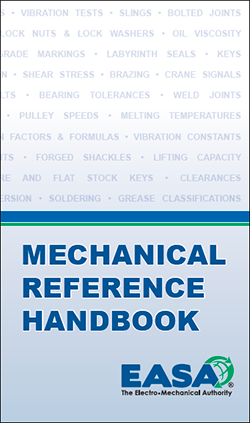
Mechanical Reference HandbookDESCRIPTION
This 94-page handbook (3.5" x 6", 9cm x 15cm) contains carefully selected materials designed to assist repair firms in their everyday work. Just as important, your customers and potential customers can use this pocket handbook as a handy reference for mechanical data for motors and driven equipment. Buy this great resource as is OR custom brand your company logo and information on the cover to turn it into a great marketing piece for your salespeople!

BUY COPIES OF THIS HANDBOOK

TABLE OF CONTENTS

Alignment
Alignment Information
Suggested Alignment Tolerances
ANSI/ASA Alignment Quality

Balancing And Vibration
Single-Plane Versus Two-Plane Balancing
Vibration Tests
Unfiltered Housing Vibration Limits
FFT Vibration Analysis
Vibration Constants
Vibration Conversion Factors
Electric Motor Vibration Diagnostic Chart

Motor Application Forumlas
Output
Shear Stress
Speed–AC Machinery 
Affinity Laws–Centrifugal Applications

Conversion Factors, Equivalencies & Formulas
Conversion Factors
Temperature Conversion Chart
Common Fractions Of An Inch–Decimal & Metric Equivalents
Prefixes–Metric System
Formulas For Circles

Bearings
Nominal Dimensions For Radial Ball Bearings
Nominal Dimensions For Cylindrical Roller Bearings
Radial Ball Bearing Fit Tolerances
Cylindrical Roller Bearing Fit Tolerances
Lock Nuts And Lock Washers For Ball Bearings

Motor Bearing Lubrication
Lubricating Oil Viscosity Conversions
NLGI Grease Compatibility Chart
Grease Classifications
Grease Relubrication Intervals

Metals And Alloys
Properties Of Metals And Alloys
Weight Formulas For Steel
Thermal Linear Expansion

Bolts
ASTM And SAE Grade Markings For Steel Bolts And Screws
Precautions For Tightening Bolted Joints
Bolt Tightening Torque Values
Tap Drills And Clearance Drills For Machine Screws

Keys And Keyseats
NEMA Keyseat Dimensions–Foot-Mounted AC & DC Machines
IEC Shaft Extension, Key And Keyseat (Keyway) Dimensions
Square And Flat Stock Keys
Standard Keyseat Sizes
Metric Keys–Standard Sizes

Belts And Sheaves
Pulley Formulas For Calculating Diameters and Speeds
Belt Installation
Belt Tensioning
Belt Deflection Force And Elongation Ratio
Standard V-Belt Profiles And Dimensions
V-Belt Sheave Dimensions
V-Belt Sheave Dimensions For AC Motors With Rolling Bearings
Application Of V-Belt Sheave Dimensions To AC Motors With Rolling Bearings
Mounting Of Pulleys, Sheaves, Sprockets, And Gears On Motor Shafts
Minimum Pitch Diameter For Drives Other Than V-Belts

Welding, Brazing And Soldering
Recommended Copper Welding Cable Sizes
Types Of Weld Joints 
Brazing
Basic Joints For Brazing
Soldering
Melting Temperatures Of Tin-Lead-Antimony Alloys
Flux Requirements For Metals, Alloys And Coatings

Slings, Wire Rope, Shackles and eyebolts
Types Of Slings
Typical Sling Hitches
Wire Rope
Spreader Bars
Lifting Capacity
Forged Shackles
Eyebolt Strength

Common Signals For Crane

Available Downloads

Pitfalls of applying generally accepted coupling manufacturers' alignment tolerances

Pitfalls of applying generally accepted coupling manufacturers' alignment tolerances

Ken Gralow
Gray Electric Co.
Schenectady, New York
Technical Education Committee Member

Shaft couplings are devices that connect two rotating shafts together. They efficiently transfer motion and power from the drive unit to the driven unit without adversely impacting either piece of rotating equipment. Under ideal conditions, both shafts should function as a continuous unit.

The design of a flexible coupling is to accommodate small amounts of shaft misalignment. Coupling manufacturers have designed their couplings to withstand the forces resulting from excessive shaft misalignment. Unfortunately, shaft alignment tolerances have sometimes been governed by the coupling manufacturers’design speecifications. These are maximum values that are dimensionally possible for a specific coupling. The coupling misalignment tolerances reported by coupling manufacturers apply ONLY to the coupling.

Available Downloads

Removal and Installation of Couplings

Removal and Installation of Couplings

Tom Bishop, PE
EASA Senior Technical Support Specialist

This article addresses methods for removal and installation of couplings on straight or tapered shafts. The most common good practice methods will be described.

Available Downloads

Reparación de Embragues y Frenos de Corrientes Parásitas

Reparación de Embragues y Frenos de Corrientes Parásitas

Chuck Yung
Especialista Sénior de Soporte Técnico de EASA

Los embragues de corrientes parásitas (acoplamiento/embrague/freno/clutch), aunque poco a poco están siendo reemplazados por la tecnología con variadores de frecuencia electrónicos (VFD) siguen en uso y requieren reparaciones (Figura 1). A medida que estos dispositivos se vuelven más raros, el grupo de expertos en ellos también se reduce, pero el lado positivo es que su naturaleza especializada asegura que quienes estén familiarizados con este tipo de equipos serán demandados durante algún tiempo.

Available Downloads

Shaft couplings: Types and applications

Shaft couplings: Types and applications

Ken Gralow
Gray Electric Co.

Shaft couplings are devices that connect two rotating shafts together. They efficiently transfer motion and power from one shaft to the other without adversely impacting either piece of rotating equipment. They should transfer constant and peak torques, be easily removed and replaced, and allow for separation of the coupled equipment. Although shaft couplings come in many shapes and configurations, they basically fall into one of two major categories: rigid (or solid) and flexible couplings.

Available Downloads